Processor node for the Agora architecture
Replacing a transputer with a standard CPU and an FPGA
1st November, 2001
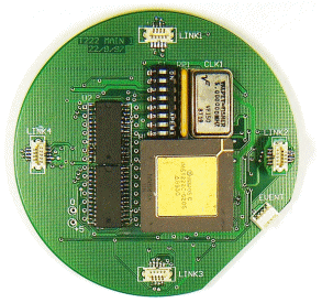

Clive Hobson and I designed a processor board to replace the transputer processor board on the QUTy mini-robot. The implementation replaced the transputer with a commercial processor (a Hitachi SH4) and a serial-link emulator housed in an FPGA.
A Replacement Transputer Node for the Agora Distributed Computing Architecture for Robotics
Clive Hobson and ; Supervised by
Smart Devices Lab, School of Computing Science, Faculty of IT, QUT
The aim of this project is to design, build and test a processor module to replace the existing Transputer node in the QUTy mini-robot. The Inmos Transputer implementation is obsolete, and is no longer in production. To enable the continued development of the Smart Devices Lab's in-house robot architecture, the obsolete components of the QUTy robot must be progressively replaced and updated.
A replacement Transputer processor module will be designed incorporating a standard Hitachi SH4 microprocessor, a programmable logic chip (FPGA) to emulate the Transputer link interface and some local memory. An evaluation board will be designed and constructed to replace the functionality but not to meet the Agora architecture form factor required by the QUTy robot. This board will be able to communicate with the existing QUTy robot via an adapter board.
The transputer architecture
A Transputer is a processing node with local memory and resources, which communicates with other Transputers via high-speed dedicated serial links. Transputers are designed to be connected in homogeneous networks, where all communication between nodes is performed over these links.
The Transputer serial links are defined as uni-directional fixed point-to-point communication channels. The communication protocol is extremely simple, with low overhead. Because all connections between Transputers are made with this standard protocol, individual nodes can perform any function required, as long as they conform to the link protocol. This serves to decouple the elements of a system, so a network of homogenous interfaces can be constructed with any topology to perform any function.
The basic unit of execution in the Transputer architecture is the process. Individual Transputers can support multiple processes with hardware scheduling. Processes communicate with each other via the same serial interface, whether they are on the same Transputer node or on different nodes.
The QUTy min-robot
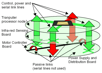
The QUTy mini-robot uses the concept of a Transputer network in its hardware architecture [3]. The hardware components are separated into individual boards which perform one function each. These boards are stacked using connectors which form the serial links between the modules. Each Transputer processor node can support up to four peripheral nodes of any type. The system power and control lines are also propagated via these connectors.
The links formed by the connector chains are fixed point-to-point. Each peripheral board has one active connector, and must be rotated so that it is the only active peripheral on that chain. The communication links are therefore static for a given hardware configuration, and cannot be modified on-line. The robot currently has a motor controller board, a power supply board, an infra-red sensing board and an RS-232 interface board.
The existing processor Transputer nodes in the QUTy robot are based around the T222 and T800 Transputers from Inmos (SGS-Thompson Microelectronics Group). These processors have a hardware micro-coded process scheduler and an interface for external memory, as well as support for the Transputer serial link interface. The T800 also has a floating-point unit. These processors ceased production in the mid 1990s.
Processor Board Architecture and Design
To fully replace the functionality of the QUTy Transputer processor nodes, support for multiple processes is required as well as conforming to the existing hardware constraints. The development of the required micro-operating system is outside the scope of this project. The outcome of this project is an evaluation board which can replace, in hardware, the existing Transputer processor nodes.
Because of the difficulty of troubleshooting internal signal layers in multi-layer circuit boards, the desing was divided into a two step approach. This project only attempted the first step of producing a logical replacement for the existing processor node. The final step in replacing the node would be to fit the logical circuit into the physical constraints of the Agora architecture.
| Feature | Evaluation board | Final (Agora) board |
| Memory | 32 kBytes SRAM | 4 MBytes SRAM |
| Board Processor | Hitachi SH4 | Hitachi SH4 |
| System Clock | 20 -> 60 MHz | 20 -> 60 MHz |
| Processor Clock | 60 -> 120 MHz | 120 MHz |
| Links | Adapter board | Agora architecture links |
| Link Interface | Spartan-II FPGA | Spartan-II FPGA |
| Size | 190x130mm | 85mm diameter circle |
| Signal layers | 2 (double-sided board) | at least 4 |
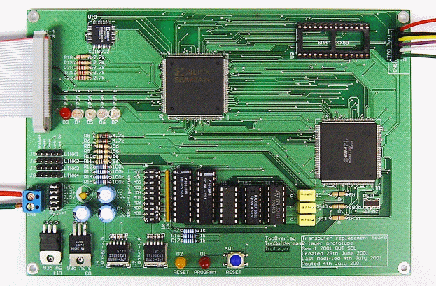
An evaluation board was developed with the same essential functionality as desired on the final board. The major differences are reduced memory capacity and a larger form factor to allow signal routing on a simple double-sided board. Efforts were made to ensure that the design of the evaluation board could be simply modified for the final board. The evaluation board has extensive hardware debugging facilities that would not exist on the final board. The Transputer links are routed off the board with a standard wide-pitch connector, and pass through an adapter board on to the existing robot. Aside from these differences, the function of the evaluation and final boards is identical. For the rest of this document no distinction will be made between the two.
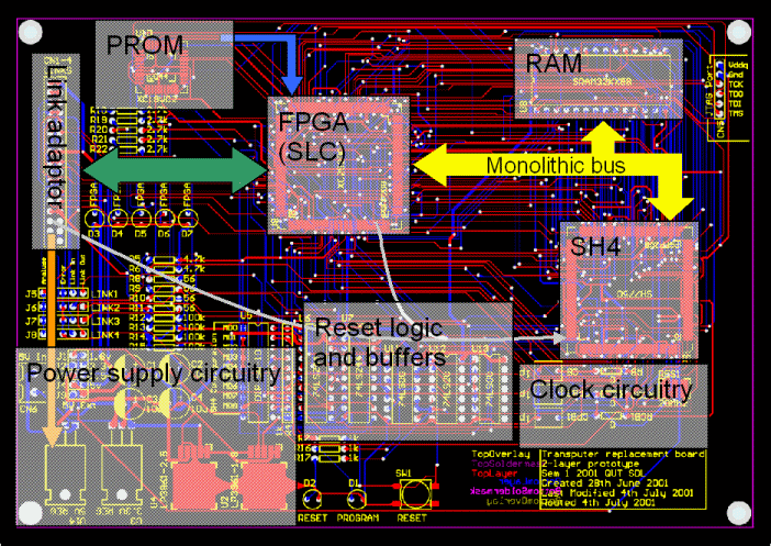
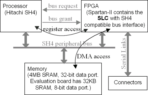
Externally, the board appears as a standard Transputer node. It has four bi-directional serial links which are compatible with the Inmos Transputer link specification. These links are managed by a Serial Link Controller (SLC) based in the FPGA. This link controller allows the data on the links to be written to and from the memory on the board. The board processor is a sophisticated Hitachi SH4 [1]. This is a high-performance low-power component suited for small robotic applications. The processor communicates with the link controller and the system memory via a standard microprocessor peripheral bus. The link controller transfers the data between the links and memory using a bus-mastering DMA (Direct Memory Access) approach.
Link Interface Design and VHDL
In February 2001 an implementation of the Serial Link Controller was made available in VHDL (a hardware description language) [4]. This implementation provided an adaptor between the Transputer serial link interface and the AMBA AHB (Advanced High-performance Bus). The AMBA bus is designed specifically for system-on-chip applications and is not compatible with the Hitachi SH4 peripheral bus [1]. The AMBA interface of the link controller had to be replaced with an interface compatible with the SH4. The SH4 peripheral bus is designed for off chip peripherals. It has fewer signals than the AMBA bus, many of which are bi-directional.
The peripheral bus interface to the link controller has to allow both access by the processor to the controller registers and DMA access to the memory by the link controller when receiving serial link data. Allowing access to the controller registers is relatively simple because the registers can be accessed in a similar way to the system RAM. DMA access to memory is considerably more complicated because the link controller must behave as a bus master. Access to the peripheral bus must be requested, granted by the processor and then released back to the processor after the DMA transfer.
There are two separate modules of the peripheral bus interface to the link controller. The module that allows the processor to read or write to the contoller registers is known as the slave component. The module that allows the link controller to control the bus for DMA transfers is known as the master component.
The slave component of the bus interface was implemented using a Finite State Machine (FSM) to keep track of the progress of the current read or write request. The master component of the bus interface was also implemented using an FSM, but is much more complicated. When the link controller requires memory access it alerts the master component, which then requests ownership of the bus. Once ownership is granted the master will make one full word DMA transfer to or from memory and then release the bus. The bus is not held between successive requests from the link controller because doing so would prevent the processor from accessing memory, preventing it from executing processes.
Future Work
A cicuit schematic and circuit board layout has been created for the final board. A future project would involve routing the connections on an appropriate number of signal layers, and then assembling and testing the board. As mentioned previously, a micro-operating system needs to be developed for the new processor node to provide process scheduling and serial link services. The micro-operating system would be a major component of further work on the replacement processor node.
References
[1] Hitachi Ltd. 2000, Hitachi SuperH RISC Engine SH7750 Series: Hardware Manual [Online]. Available: http://www.hitachi.co.jp/Sicd/English/Products/micom_all/l001e.htm [2001, September 5].
[2] Inmos Ltd. 1992, The Transputer Databook, SGS-Thompson Microelectronics Group, Italy.
[3] Malmstrom, K. 2001, Thesis for the award of a PhD in Mechanical Engineering, Queensland University of Technology, Brisbane.
[4] Meiners, H. 2001, Hardware Support for a "Communicating Process Architecture" in Autonomous Control Systems, Paderborn University.
Note: The first half of this Abstract was supplied by Dylan Muir, the second half was supplied by Clive Hobson.